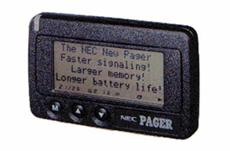
 ERMES was a European Paging system. In the early 1990s, at a time when paging was taking off, the European Union issued a directive (90/544/EEC) which forced all EU Member States to set aside the frequency range 169.4 - 169.8 MHz for paging services. Ultimately text messaging using SMS came along at the same time and made paging obsolete before any EU-wide services were introduced. Fifteen years later, in 2005 the directive was repealed.
- TFTS was the terrestrial flight telecommunications service. The European Radiocommunications Committee set aside 1670 - 1675 and and 1800 - 1805 MHz for TFTS in 1992 (ERC Decision (92)01). TFTS was meant to be a network of ground based transmitters which would provide voice and basic data connectivity to aircraft. This decision was withdrawn ten years later in 2002 when no networks whatsoever had been rolled-out and satellite communication for aircraft had become easier and far less expensive.
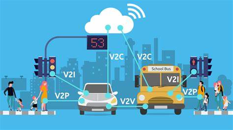
Arguably the same thing is now happening with V2X technologies. V2X (Vehicle to Everything, sometimes also known as ITS, intelligent transport systems) represents a number of different solutions for connection to, and between, road vehicles to enhance road safety and improve driverless driving. Many countries around the world (including the USA, Japan and Europe) set aside 75 MHz of spectrum from 5850 - 5925 MHz for this purpose (as per ITU Recommendation M.2121). However in 2020, the FCC reduced the amount of spectrum available from the original 75 MHz, to just 30 MHz citing the availablity of other technologies such as radar, lidar and video cameras as delivering many of the safety-related capabilities that V2X was intended to provide. Japan has recently done likewise.
In Europe, CEPT has recommended 5855 - 5925 MHz for V2X/ITS technologies (ECC/REC/(08)01), and harmoinsed the use of the frequency range 5875 - 5925 MHz whereas the European Commission has harmonised only the frequency range 5875 - 5905 MHz (Commission Decision 2008/671/EC). Even the specification for the technology (ETSI EN 302 571) hedges its bets on which piece of spectrum will or could be used for this technology.
Notwithstanding all this, and the fact that the spectrum has been available for 15 years, there has been little to no take-up of the technology. The C-Roads initiative shows (on the 'implemented services' page) the extent of coverage of V2X equipped roads. With the exception of one or two highways, most deployments are city based experiments. The fact that the technology is yet to become standard in new vehicles is leading to classic 'chicken and egg' situation where manufacturers are reluctant to put the technology in cars because there is nothing for them to connect to, and highways agencies are reluctant to install any roadside infrastructure as vehicles are not equipped with it. Furthermore, there is confusion about the business model for the roadside equipment. Is this a safety responsibility of the road authorities, or could it be a commercial provider offering advanced weather and traffic reports who builds it out?
Alongside this confusion, 5G mobile technology is slowly being rolled-out and has the capability to provide the kind of connectivity between vehicles and the roadside that V2X/ITS promises (and the business model is clear). Equally, in-car radars now have the ability to communicate with neighbouring vehicles to provide information on when the driver is applying the breaks, for example. The case for V2X/ITS is therefore rather nebulous and it seems ever more likely that the spectrum set-aside for that purpose will fester for a few more years before pressure mounts and it is decided that V2X, like ERMES and TFTS has evaporated into nothingness.
What the spectrum could then be used for is a question for another day, however one option may be CBTC (communication based train control) which often uses unlicensed 2.4 and 5.8 GHz frequencies and could do with a 'safer' home given it is used to control the movement of (mostly metro) trains. China is considering the possible use of the frequency range 1785 - 1805 MHz for CBTC which, if you've been following this article, you will realise includes some of the original TFTS spectrum. And thus the circle is squared.]]>
;)
;)
;)
;)
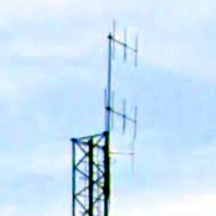 It is not easy to see from the picture above and to the right, however using Google Street View it is possible to get a side look at the mast. Mounted on top are two, three element, vertically polarised antennas pointing roughly north west (as they would need to, to provide coverage in Ypres from the transmitter site). Again, it is difficult to tell, but a working assumption might be that these are the antennas used for TOP Radio, not least as they are the only ones that would be near the 30 metre height that the records suggest that they should be mounted at. It may be that the '100 Watt' power restriction has been interpreted as 100 Watts to the antenna, rather than 100 Watts e.i.r.p.
;)
;)
;)